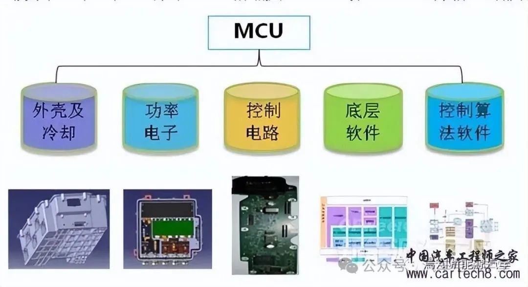
The Motor Control Unit (MCU) is a core power electronic component unique to new energy vehicles. It receives vehicle driving control commands from the Vehicle Control Unit (VCU) to regulate the electric motor's torque and speed, thereby propelling the vehicle. Additionally, the MCU converts the direct current (DC) energy from the power battery into the required high-voltage alternating current (AC) to drive the motor, while also providing motor system fault diagnosis, protection, and storage functions.
The MCU has numerous configurable parameters, each with a specific range. Improper settings of individual parameters—often configured via CAN communication or an emulator—can lead to the MCU malfunctioning. Therefore, it is essential to correctly set the relevant parameters.
Control Mode: This refers to speed control, torque control, PID control, or other methods. After selecting a control mode, static or dynamic identification is generally required based on control accuracy.
Minimum Operating Frequency: This is the minimum speed at which the drive motor operates. At low speeds, the motor's cooling performance is poor (for air-cooled types), and prolonged operation at low speeds can lead to motor damage. Additionally, at low speeds, the current in the cables increases, causing them to heat up.
Maximum Operating Frequency: Typical MCUs have a maximum frequency of up to 60Hz, with some reaching 400Hz. High frequencies cause the drive motor to operate at high speeds, which may exceed the rated speed of standard motors, potentially damaging bearings and affecting the rotor's ability to withstand centrifugal forces.
Carrier Frequency: Higher carrier frequencies result in greater high-order harmonic components, closely related to factors such as cable length, motor heating, cable heating, and IGBT heating.
Motor Parameters: The MCU sets parameters like motor power, current, voltage, speed, and maximum frequency, which can be directly obtained from the motor's nameplate.
Skip Frequency: At certain frequency points, resonance may occur, especially in taller installations. When controlling compressors, it's important to avoid the compressor's surge point (e.g., in air conditioning compressors).
Acceleration and Deceleration Time: Acceleration time refers to the duration for the output frequency to rise from 0 to the maximum frequency, while deceleration time is the duration for it to fall from the maximum frequency to 0. These times are typically determined by the rise and fall of the frequency setting signal. During acceleration, the rise rate of the frequency setting should be limited to prevent overcurrent, and during deceleration, the fall rate should be limited to prevent overvoltage.
Torque Boost: Also known as torque compensation, this method compensates for reduced torque at low speeds due to the motor's stator winding resistance by increasing the low-frequency range (f/V). Setting it to automatic allows the voltage to automatically increase during acceleration to compensate for starting torque, ensuring smooth acceleration.
Electronic Thermal Overload Protection: This function protects the motor from overheating by calculating the motor's temperature rise based on operating current and frequency. It is suitable only for "one-to-one" applications. The electronic thermal protection setting value (%) is calculated as:
Frequency Limitation: This defines the upper and lower frequency limits of the MCU's output. Frequency limitation prevents equipment damage due to incorrect operations or faults in external frequency setting signal sources. In applications, it should be set according to actual conditions. This function can also serve as a speed limiter by setting the MCU's upper frequency to a specific value, thereby limiting the maximum vehicle speed to a fixed, lower operating speed.
Torque Limitation: This includes drive torque limitation and braking torque limitation. It calculates torque based on the MCU's output voltage and current, significantly improving the impact load recovery characteristics during acceleration, deceleration, and constant-speed operation. Torque limitation enables automatic acceleration and deceleration control.
The drive torque function provides strong starting torque. During steady-state operation, the torque function controls the motor's slip, keeping the motor's torque within the maximum set value. When the load torque suddenly increases, even with a short acceleration time setting, it won't trigger high-voltage system power-off protection. A larger drive torque is beneficial for starting, with settings between 80% and 100% being appropriate.
The braking torque setting value determines the braking force; a smaller value results in greater braking force, suitable for rapid acceleration and deceleration scenarios. If set too high, overvoltage alarms may occur. For instance, setting the braking torque to 0% can make the regenerative energy added to the main capacitor close to 0, allowing the drive motor to decelerate to a stop without using braking resistors and without overvoltage protection. However, on certain loads, setting the braking torque to 0% may cause brief idling during deceleration, leading to repeated MCU starts, significant current fluctuations, and, in severe cases, MCU faults. This requires attention.