# I. Definition and Main Manufacturers of ECU
Originally, ECU stood for engine control unit, specifically referring to the electronic control system of fuel-injected engines. However, with the rapid development of automotive electronics, the definition of ECU has undergone significant changes, now standing for electronic control unit, which generally refers to all electronic control systems in a car. These can be steering ECUs, speed control ECUs, air conditioning ECUs, etc. The original engine ECU is often referred to as EMS (engine management system) by many companies. With the increasing degree of automation in automotive electronics, more and more ECUs are involved in automotive parts, and the complexity of the wiring between them has also increased sharply. To simplify, refine, and miniaturize the circuits, the CAN bus has been introduced into automotive electronics. The CAN bus can form a local area network for the information transfer between multiple ECUs on the vehicle, effectively solving the problem of complexity in line information transfer. Currently, Bosch, Delphi, Denso, and Continental are leaders in the automotive ECU industry.
# II. Basic Composition of ECU
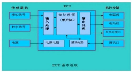
Simply put, an ECU consists of a microcomputer and peripheral circuits. The microcomputer is a unit that integrates a microprocessor (CPU), memory, and input/output interfaces on a single chip. The main part of the ECU is the microcomputer, and the core component is the CPU. The input circuit accepts signals from sensors and other devices, filters, processes, and amplifies the signals, and then converts them into a certain voltage level of input. The signals sent from the sensors to the ECU input circuit include both analog and digital signals. The analog-to-digital converter in the input circuit can convert analog signals into digital signals, which are then transmitted to the microcomputer. The microprocessor processes the preprocessed signals mentioned above and sends the processed data to the output circuit. The output circuit amplifies the power of the digital information, and some also need to be restored to analog signals to drive the controlled adjustment servo components, such as relays and switches. Therefore, an ECU is actually an electronic control unit (Electronic Control Unit), which consists of an input processing circuit, microprocessor (microcontroller), output processing circuit, system communication circuit, and power supply circuit.
In detail, an ECU generally consists of a CPU, extended memory, extended IO ports, CAN/LIN bus transceiver controllers, A/D D/A converters (sometimes integrated in the CPU), PWM pulse width modulation, PID control, voltage control, watchdog, heat sink, and other electronic components. ECUs with specific functions also carry components such as infrared transceivers, sensors, DSP digital signal processors, pulse generators, pulse distributors, motor drive units, amplification units, and strong and weak electrical isolation. The entire circuit board is designed and installed in an aluminum box, which is conveniently mounted on the vehicle body sheet metal with clips or screws. ECUs generally use universal and functionally integrated CPUs that are easy to develop; software is generally written in C language, and rich driver libraries and function libraries are provided, along with programmers, emulators, simulation software, and software for calibration.
# III. Basic Organizational Structure of ECU
The automotive electronic control system includes hardware and software parts. The hardware consists of electronic control units (ECUs) and their interfaces, sensors, actuators, display mechanisms, etc.; the software is stored in the ECU and controls the electronic control system to complete real-time measurement and control functions. The circuit structure of most electronic control systems in cars is similar, and the change in control functions mainly depends on the software and the functional changes of input and output modules, which vary with the tasks that the control system needs to accomplish. The basic structural system of an ECU includes an input processing circuit, microprocessor, output processing circuit, and power supply circuit.
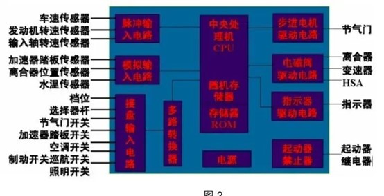
In the input processing circuit, the input signals of the ECU mainly have three forms: analog signals, digital signals (including switch signals), and pulse signals. Analog signals are converted into digital signals through A/D conversion to provide to the microprocessor. The control system requires high resolution and accuracy (>10 bits) for analog-to-digital signal conversion. To ensure the real-time performance of the measurement and control system, the sampling interval is generally required to be less than 4ms. Digital signals need to be level-converted to obtain signals accepted by the computer. The input circuit also converts input signals that exceed the power supply voltage, vary between positive and negative voltages, have high oscillation or noise, and have fluctuating voltages. The microprocessor first completes the A/D conversion of sensor signals, measurement of periodic pulse signals, and other input processing related to car driving state signals, and then calculates and controls the required output values, sending control signals to the actuators in a timely manner as required. In the past, most microprocessors were 8-bit and 16-bit, with a few using 32-bit. Now, 16-bit and 32-bit machines are more commonly used.
In the output circuit, the signal output by the microprocessor is often used to control solenoids, indicator lights, stepper motors, and other actuators. The output signal of the microprocessor has low power and uses a +5v voltage. Most of the actuators in the car use the battery as the power supply, and the microprocessor's control signal needs to be processed by the output processing circuit before driving the actuator. In the power supply circuit, traditional car ECUs generally have a battery and a built-in power supply circuit to ensure that the microprocessor and its interface circuits work at a stable +5v voltage, thereby ensuring the normal operation of the system, even when the battery voltage fluctuates greatly during engine start-up conditions. Electric vehicles are generally powered by batteries.
In terms of software, the control program of an ECU includes the following aspects: calculation, control, monitoring and diagnosis, management, and monitoring. It executes the control mode as shown in Figure 3.
# IV. Similarities and Differences Between Traditional and Electric Vehicle ECUs
Traditional automotive ECUs are mainly used for the following aspects:
1. Engine control, ignition, valve timing adjustment, throttle adjustment, starter motor adjustment, clutch adjustment, fuel injection adjustment, etc.
2. Continuously variable transmission control, belt position adjustment, speed adjustment
3. Automatic transmission control, relay or solenoid reversing valve control
4. Active suspension, adjustment of air spring rigidity and damping hole size
5. Driving force and anti-skid control, including ABS anti-lock braking system, EBD electronic brake force distribution, EBA emergency brake assist system, ESP electronic stability program, TCS traction control system, MSR engine resistance torque control, EDS electronic differential lock, OBD on-board diagnostic system, DSC dynamic stability control system
6. Body control BCM, including window lifting (including force sensor - for safety), sunroof folding and sliding, seat lifting adjustment, wipers, defrosters, etc.
7. Air conditioning, heating, ventilation control, including compressor, condenser, evaporator fan, expansion valve, etc.
8. Electronic switches and lighting, including headlights, taillights, display backlight, acceleration and deceleration, radio, CD, etc.
9. ACC electronic active cruise control
10. Airbag self-diagnosis and detonation control
11. Active seat belt self-diagnosis and detonation control, retraction seat belt detonation control
12. EPS steering control, HPS steering control
13. TPC tire pressure control
14. Car instruments
15. Anti-theft alarm
16. Vehicle height balance system
17. Smart sensors, i.e., sensors with ECUs
Electric vehicles refer to vehicles that use on-board power as the power source, drive the wheels with electric motors, and meet various requirements of road traffic and safety regulations. Due to their relatively small impact on the environment compared to traditional cars, they have broad prospects as new energy vehicle models optimized on the basis of traditional cars. The ECU control of electric vehicles differs from traditional ones in the following ways:
1. Removed engine control and added motor and its control system
2. Battery and its management system
3. On-board charger
4. Body low-speed bus control system
5. On-board recorder and operation analysis system
6. Fault diagnosis and safety management system
7. Vehicle safety operation monitoring system
8. Vehicle power comprehensive control system
9. TCU control applied to AMT
# V. Future Development of ECU
Over the past decade or so, the development of automotive intelligence and informatization has resulted in an increasing number of ECU chips used. From traditional engine control systems, airbags, anti-lock braking systems, electric power steering, vehicle electronic stability systems; to intelligent instruments, entertainment audio-visual systems, auxiliary driving systems; as well as electric drive control, battery management systems, on-board charging systems in electric vehicles, and the booming in-vehicle gateways, T-BOX, and autonomous driving systems, etc.
The traditional automotive electronic and electrical architecture is distributed, with various ECUs in the car connected together through CAN and LIN buses. The total number of ECUs in modern cars has rapidly increased to dozens or even hundreds, making the system increasingly complex and nearing its limit. Under the trend of software-defined vehicles and the development of automotive intelligence and connectivity, this distributed EEA based on ECU has increasingly exposed many problems and challenges.
To solve the problems of distributed EEA, people have gradually integrated many similar and separate ECU functions into a processor hardware platform with stronger performance than ECU, which is the automotive "Domain Control Unit (DCU)." The emergence of domain controllers is an important sign of the evolution of automotive EE architecture from distributed EEA based on ECU to domain centralized EE architecture.
The domain controller is the core of each functional domain of a car, mainly composed of a domain main control processor, operating system, and application software and algorithms. Platformization, high integration, high performance, and good compatibility are the main core design ideas of domain controllers. Relying on high-performance domain main control processors, rich hardware interface resources, and powerful software functional characteristics, domain controllers can integrate core functions that originally required many ECUs, greatly improving system functional integration. In addition, standardized interfaces for data interaction can greatly reduce development and manufacturing costs.
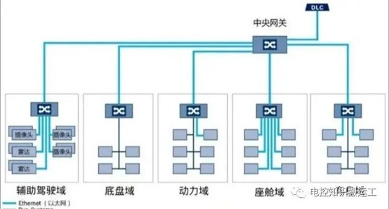
Regarding the specific division of functional domains, different automotive OEMs will divide into several different domains according to their own design concepts. For example, BOSCH divides into five domains: Power Train, Chassis, Body/Comfort, Cockpit/Infotainment, and ADAS. This is also the most classic five-domain centralized EEA. Some manufacturers further integrate on the basis of the five-domain centralized architecture, merging the original powertrain, chassis, and body domains into a vehicle control domain, thus forming a three-domain centralized EEA, i.e., Vehicle Domain Controller (VDC), Intelligent Driving Domain Controller (ADC, ADAS\AD Domain Controller), and Intelligent Cockpit Domain Controller (CDC). Volkswagen's MEB platform and Huawei's CC architecture both belong to this type of three-domain centralized EEA.